Coaxial Cavity Filters
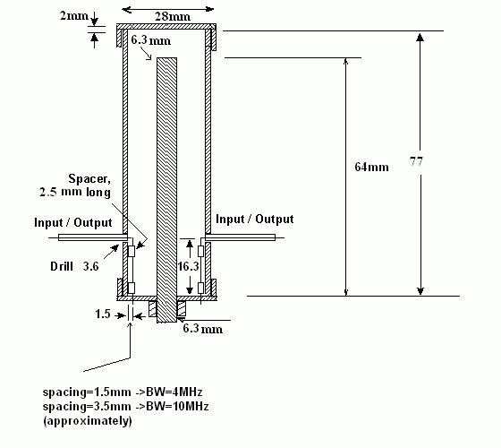
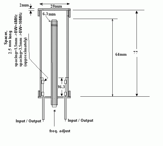
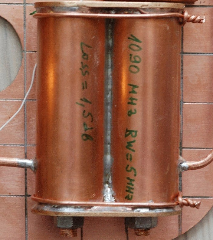
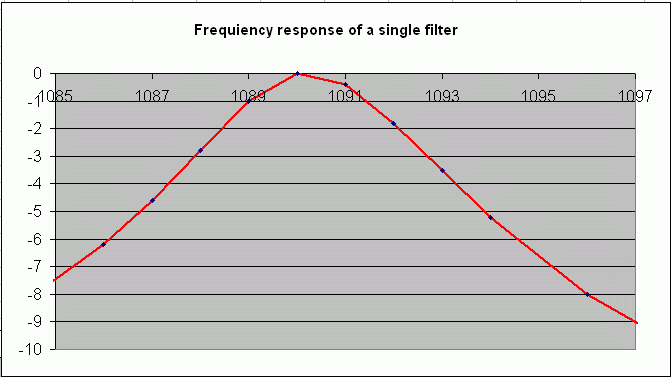
I give you two versions of the single filter. The difference is in the location of the terminals. I have used both types, they both work the same.
I have no recipe for easy making those filters. It's always hard. You may use a butane torch or a soldering iron; it's up to you.
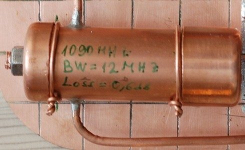
All the materials are made of copper in my case. If you can silver-plate them, fine. Otherwise, make sure that after all the soldering is done you polish the inside to a shine.
Don't use bronze! Brass is OK.
It takes me something like 2 hours to make one filter and another 1/2 to one hour to tune it properly in terms of bandwidth and central frequency.
Bandwidth is adjusted by changing the spacing (see pictures) symmetrically of both wires. The wider the bandwidth, the lower the insertion loss.
Central frequency is adjusted by changing the length of the central rod.
Don't be afraid! If I have done it, you could do it, too!
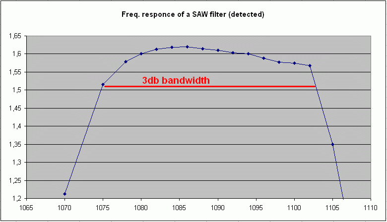
You may wonder why I didn't build even a narrower filter (say, 3MHz) to further improve the S/N ratio.
I'll give you three reasons.
First, It's because of the temperature stability (may be a problem for portable designs).
Second, the Mode-S transponders are allowed to transmit from 1089 to 1091 MHz. A narrow filter may not work fine with all the transponders.
Third, it's the shape of the detected pulses. Passed through a narrow-band filter, the pulses are very hard to detect properly since they blend into one long pulse at the output of the logarithmic detector.
You have to know that it's best to fine-tune the filters after connecting them. Only then will you have the best performance. (This is because the antenna and the amplifier stages are not perfectly matched loads.)
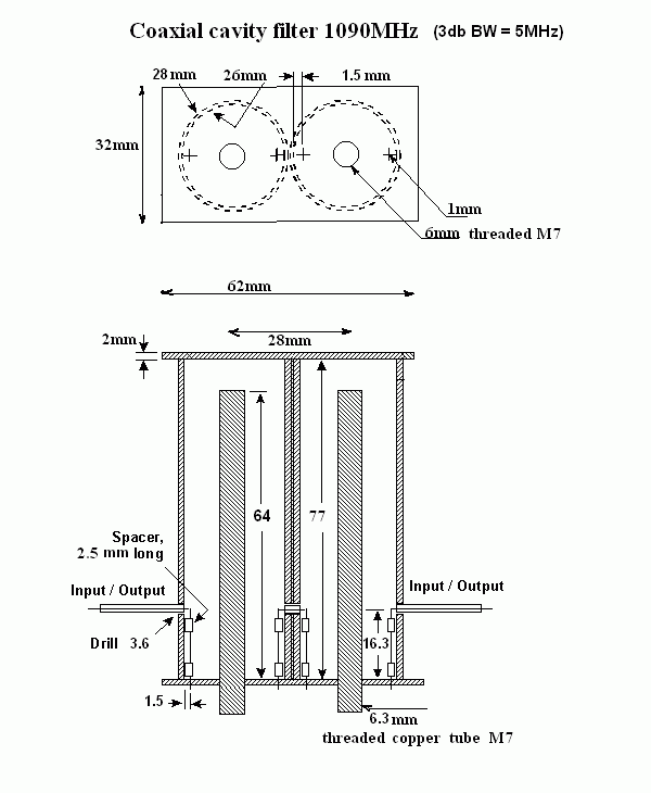
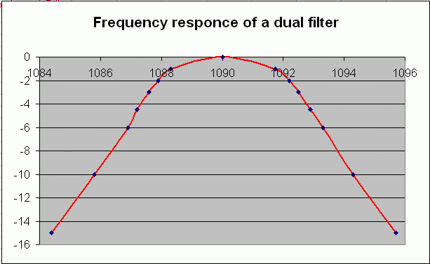
This is a dual coaxial cavity filter.
It takes more time to tune it, but the out-of-band rejection is much better.
